RAIL CONSULTANCY
Case Study: Camden Lock, London
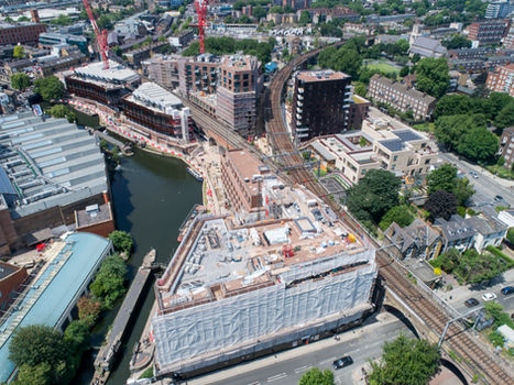
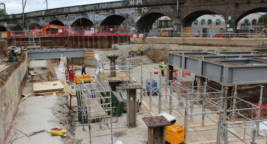
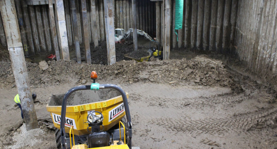
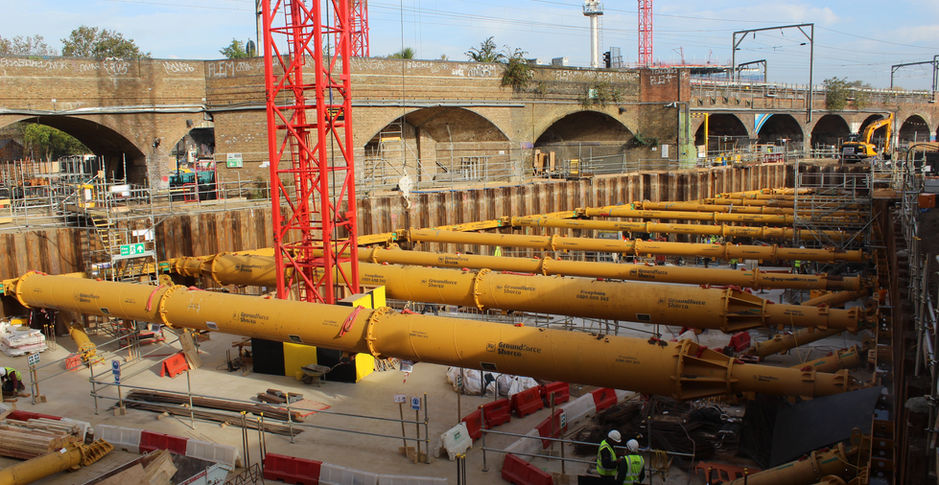
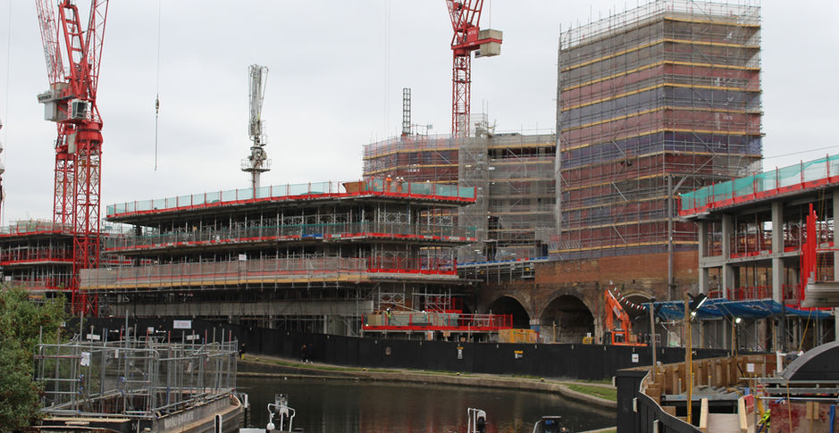
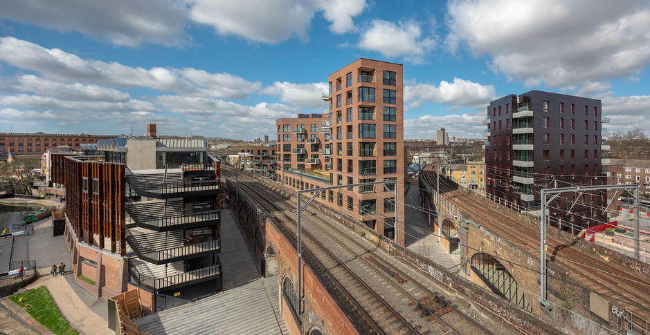
We have chosen to showcase the Camden Lock project, also known as Hawley Wharf, as a case study, due to a number of different disciplines within our team all being involved with a variety of services. Whilst at first glance from the three images below, this looks just like any other project, it's only when you understand the complexities that you start to consider all of the things that you need to consider in your project.
The site at Camden Lock Village was split into zones by way of four railway tracks running on two separate viaducts. These were 150 years old and were extremely fragile. Separately, the tunnels of both branches of the Northern Line ran under the road at the East and West of the site. The remainder of the site was logistically constrained by the Regent's canal to the South and roads around the North, East and West. In addition, the site was adjacent to and traversed by National Grid assets, a redundant river bed and a new primary school.
During the pre-construction period, the team produced a risk register to review and consider each of these risks in turn.
How to excavate a 16 meter deep basement below Building C between to live railway viaducts
At first glance, the building may appear to be a relatively simple structure, being just 8 storeys high. However, the building sits on top of a 16 metre deep, 2 storey basement, which required excavation within the zone of influence of the 150 year old Network Rail viaducts.
As the railway viaduct settlement had to be limited to a very small safety margin, a vast array of monitoring equipment was set up to monitor the viaducts on all axes in real time. The monitoring scheme for the site included 6 automatic total stations monitoring the viaducts in real time, 42 inclinometers, 20 wireless tiltmeters, 14 vibration monitoring units and a team of technicians and engineers. In addition, due to the potential for the ground movement during construction, tunnel deformation monitoring equipment was installed within the London Underground Northern Line tunnels. The data from this equipment was critical in managing the sequence of excavations and assisted in the addition of measures as required to ensure the continued safe operation of the railway thoughout construction.
Due to the basement requiring the excavation of 58,250 cubic metres of London clay, a top down construction was required as the basement area was too large to consider traditional propping to support the viaducts. The agreed sequence was therefore to install 292 contiguous piles to form the perimeter of the basement box, each of 750mm diameter. Internally there were 52 plunge columns encased in a 1,800mm diameter foundation plus a further 34 bearing piles each of 750mm diameter. The piles extended up to 36 meters into the ground.
Prior to excavation the ground floor slab was to be installed first to provide the lateral support for the viaducts prior to excavation commencing. The 263 meter long capping beam was so deep in certain sections that it required sheet piles installed to support the first phase of the capping beam excavation. The capping beam was formed to incorporate 133 tons of reinforcement, prior to 600 cubic meters of concrete being poured. The plunge columns were interconnected with 376 tons of steel stanchions, prior to decking a 3,400 square meter ground floor slab with a further 450 tons of reinforcement and 1,800 cubic meters of concrete.
How to excavate a basement for Building A & D whilst also excavating 16 meters for Building C
At the same time as digging Building C's basement 16 meters deep on one side of the Southern Viaduct, Building A and D were also requiring the excavation of their basement between the viaduct and the Regent's Canal.
The basements of Building A and D were traditional open excavations, whilst again they look simple, the design of the propping was a delicate task as the props were designed to support the viaduct and train loads during construction. Building A had 190 linear meters of sheet piling to form the perimeter, with a further 180 bearing piles internally.
Following installation of the Phase 1 propping, the basement was excavated, with the removal of a further 11,500 cubic meters of London clay from Building A1 and 8,250 cubic meters from Building D. King posts were then case into the basement slab allowing the installation of the Phase 2 raking propping, which in turn released the Phase 1 props for the installation of the lower ground floor slab. At a later date once the structure had cured, the raking props could be removed from the basement via mole holes left within the structure.
The data from all of the monitoring equipment was monitoring continually and influenced decisions with Network Rail to ensure that they had the confidence to allow the construction to progress, whilst at the same time continuing to run freight and passenger trains along the four railway lines.
How to excavate adjacent to and through the viaducts to connect the sitewide services
As well as the challenge of excavating basements and constructing buildings immediately adjacent to the railway viaducts, the whole development was feed with services from the centrally located energy centre in the basement of Building C. The services required excavation and installation at great depth, between the buildings, alongside the viaducts and through many of the arches. Each viaduct was also then provided with a number of services for the provision of supplies for future retail units.
The services included, foul drainage, surface water drainage, high voltage electricity serving the sub-stations, low voltage power, gas, lighting, district heating, district cooling, sprinkler pipework, water, data cabling for security and communications and telephone. Due to the constrained routes the coordination and routing of services was critical. However, due to the depth of the installation of many services, special measures such as sheet piling, trench boxes and limited excavation lengths were required. The trickiest element of the installation was where services crossed from one building to another beneath the viaduct arches. In these instances restricted headroom piling rigs installed mini piles to form capping beams through the arches. Once the piles and capping beams had reached strength they were propped and trenches excavated for the installation of services, thus negating the need for directional drilling, but still maintaining integrity to the 150 year old viaducts.


